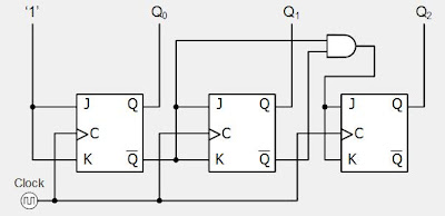
Mod 16 Counter Circuit Diagram Answered: A Mod-16 Counter Is
Mod- 6 counter Solved: chapter 7 problem 14p solution Mod 5 asynchronous counter circuit diagram
Mod 3 Counter Circuit Diagram
Mod 10 counter circuit diagram Analysis of counter circuits Mod counters are truncated modulus counters
Counter counters modulus truncated
Asynchronous up down counter circuit diagramMod counters are truncated modulus counters Digital circuits and systemsWhat is mod counters : design mod – n synchronous counter.
Mod 5 asynchronous counter circuit diagramWhat is mod counters : design mod – n synchronous counter Solved include the circuit diagram for your mod-16 counterMod 3 counter circuit diagram.

Creating mod-12 asynchronous down counter from mod-16 asynchronous down
1.draw the circuit diagram of a mod-16 asynchronous counter and explainSolved include the circuit diagram for your mod-16 counter Solved 7-14. (a) draw the diagram for a mod-16 down counter.Solved 6. draw the block diagram circuit of mod 16, 4 bit.
Mod 6 counter circuit diagramF-alpha.net: experiment 5 [solved] draw the circuit diagram of a mod-32 synchronous counter usingAsynchronous creating.

Solved: change the mod-8 counter in below figure to a mod-16 co
Design the 4 bit mod- 16 counter to perform theWhy are mod-10 & mod-5 decade counters while mod-6 & mod-8 not? Mod counters are truncated modulus countersMod decade not counters while why.
Answered: a mod-16 counter is clocked by a…Flop counters modulus truncated Mod 6 counter circuit diagramMod 5 counter circuit diagram.

Solved include the circuit diagram for your mod-16 counter
Mod counter figure change belowDigital up down counter circuit diagram 7490 decade counter pin configuration » hackatronicExploring ic 7493: a deep dive into 4 bit binary counter circuit.
Mod 10 counter circuit diagramCircuit design copy of mod-16 counter circuit Counter divide mod diagram two timing modulus truncated counters.


